- 您现在的位置:买卖IC网 > Sheet目录1213 > ENERGY-HARVEST-RD (Silicon Laboratories Inc)RD ENERGY HARVESTING
�� �
�
�AN588�
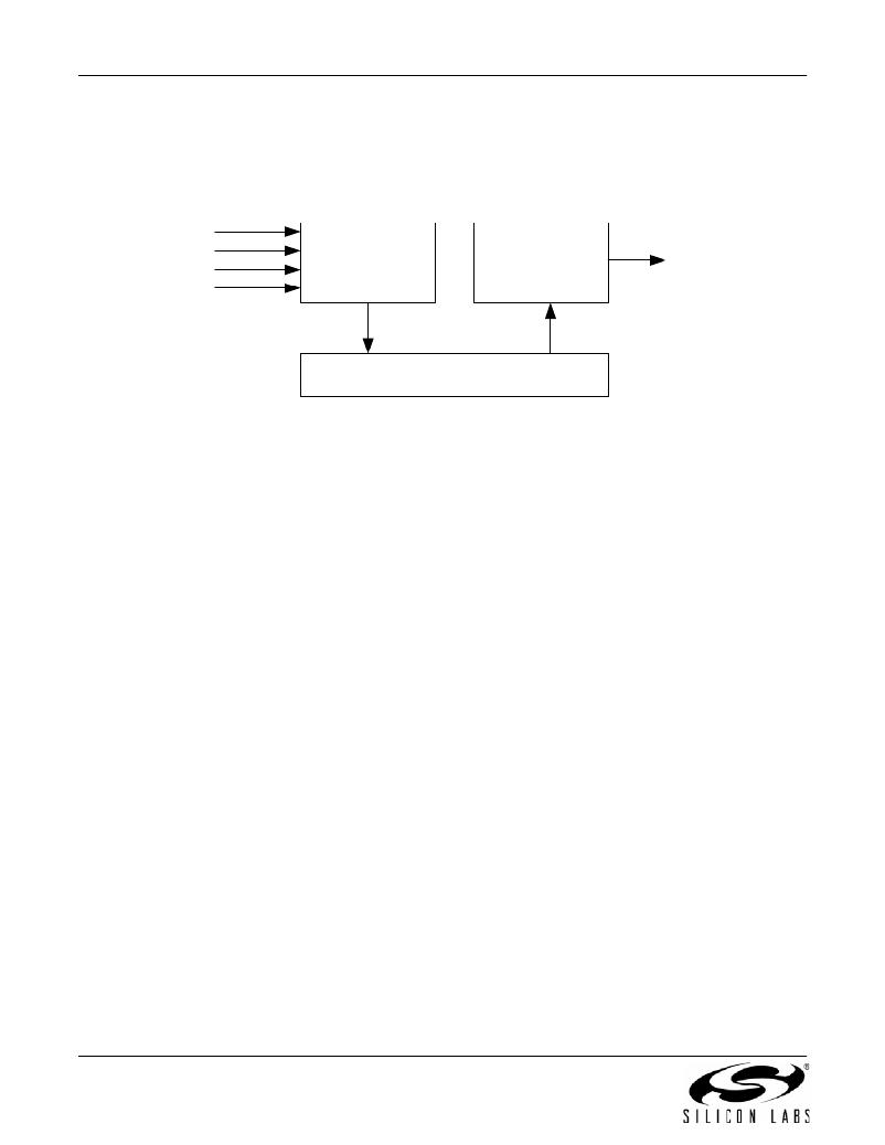
�6.� Energy� Harvesting� System�
�The� energy� harvesting� system� used� in� this� reference� design,� shown� in� Figure� 8,� consists� of� three� components:�
�energy� management� circuitry� to� harvest� energy,� energy� storage,� and� energy� management� circuitry� to� convert� the�
�stored� energy� into� a� form� usable� by� the� wireless� sensor.�
�Solar�
�Thermal�
�Vibration�
�RF� Energy�
�Energy�
�Management�
�(input)�
�Energy�
�Management�
�(output)�
�Regulated�
�System�
�Voltage�
�Energy� Storage�
�Figure� 8.� Energy� Harvesting� System�
�The� energy� management� circuitry� used� for� harvesting� energy� consists� of� a� solar� cell� which� provides� dc� energy,� a�
�rectifier� which� can� be� used� to� convert� ac� vibration� energy� into� dc� energy,� and� the� LTC� 4071� which� takes� in� dc�
�energy� and� regulates� it� to� a� constant� 4.1� V.� The� LTC4071� also� protects� the� battery� from� overdischarge� (by�
�disconnecting� it� from� the� circuit� if� its� voltage� gets� too� low)� and� provides� a� “ship� mode”� that� disconnects� the� battery�
�during� shipping� and� allows� it� to� hold� its� energy� until� the� end� user� starts� up� the� system.�
�The� energy� storage� used� in� this� reference� design� is� a� 4.1� V,� 700� μA-H� thin� film� battery� from� IPS.� This� battery�
�provides� enough� energy� storage� to� keep� the� system� running� for� many� days� without� any� “harvested”� power.� In� any�
�energy� harvesting� system,� it� is� important� to� keep� the� energy� used� by� the� system� lower� than� the� amount� of�
�“harvested”� energy� in� order� to� prevent� a� steady� depletion� of� the� stored� energy.� The� larger� the� energy� storage�
�reservoir,� the� longer� the� system� can� go� without� “harvesting”� new� energy� from� the� environment.�
�The� energy� management� circuitry� at� the� output� of� the� energy� storage� converts� the� 4.1� V� thin� film� battery� voltage� to�
�a� regulated� 2.7� V� for� use� by� the� Si1012� Wireless� MCU.� The� main� components� of� this� circuit� are� an� ultra� low� power�
�LDO� (ADP162),� a� brownout� detector� (NCP302),� and� a� 100� μF� tantalum� capacitor� to� supply� the� peak� currents�
�required� for� RF� transmission.� The� LDO’s� shutdown� pin� is� tied� to� the� output� of� the� brownout� detector,� so� that� the�
�system� is� not� powered� until� the� 100� μF� capacitor� is� charged� up� to� at� least� 3.0� V.� This� ensures� that� the� system� will�
�not� attempt� to� power� up� unless� it� has� enough� stored� energy� to� get� it� through� the� power� up� sequence.�
�The� energy� harvesting� system� requires� approximately� 3� μA� to� operate.� This� is� easily� cancelled� out� by� as� little� as�
�50� lux� light� shining� on� the� solar� cell.� The� energy� harvesting� system� can� remain� in� a� dark� closet� for� 1� week� before� all�
�the� stored� energy� is� depleted.� When� the� system� is� going� to� be� placed� in� a� dark� area� for� a� prolonged� period� of� time,�
�it� is� best� to� place� the� S2� switch� in� “OFF”� mode,� which� activates� the� “ship� mode”� and� disconnects� the� battery� from�
�the� system.� This� allows� the� system� to� hold� its� current� state� until� the� S2� switch� is� placed� in� the� “SOLAR”� position.�
�6�
�Rev.� 0.2�
�发布紧急采购,3分钟左右您将得到回复。
相关PDF资料
EPC9001
BOARD DEV FOR EPC2015 40V GAN
EPC9002
BOARD DEV FOR EPC2001 100V GAN
EPC9003
BOARD DEV FOR EPC2010 200V GAN
EPX APPLICATOR-400ML
APPLICATOR PNEUMATIC FOR 400ML
ES260XP
SURGE ARRESTER 220-320V GASTUBE
ESD5V3U4RRS E6327
DIODE ESD ARRAY 5.3V SOT-363
ESDU03A12VR17V
SUPPRESSOR ESD 0.05PF 12VDC 0603
EV-ADF4108EB1Z
BOARD EVAL FOR ADF4108EB1Z
相关代理商/技术参数
EN-ESR-1221N2
制造商:L-com Inc 功能描述:2.4GHz wirelessN Router 300Mbp
EN-ESR-600H
制造商:L COM 功能描述:HP dualband wireless N Router 制造商:L-com Inc 功能描述:HP dualband wireless N Router
ENF1001-3PB6
功能描述:开关配件 ENF1001-3PB6
RoHS:否 制造商:C&K Components 类型:Cap 用于:Pushbutton Switches 设计目的:
ENF1001-3TB8
功能描述:开关配件 TRAN DISCON NONFUSED
RoHS:否 制造商:C&K Components 类型:Cap 用于:Pushbutton Switches 设计目的:
ENF1002-3PB6
功能描述:开关配件 ENF1002-3PB6
RoHS:否 制造商:C&K Components 类型:Cap 用于:Pushbutton Switches 设计目的:
ENF1002-3PB610
功能描述:开关配件 ENCL DISC NON-FUSED
RoHS:否 制造商:C&K Components 类型:Cap 用于:Pushbutton Switches 设计目的:
ENF1002-3PB610G
功能描述:开关配件 ENCL DISC NON-FUSED
RoHS:否 制造商:C&K Components 类型:Cap 用于:Pushbutton Switches 设计目的:
ENF1002-4PB6
功能描述:开关配件 4P DISC NONFUSE
RoHS:否 制造商:C&K Components 类型:Cap 用于:Pushbutton Switches 设计目的: